DIY POE Patch
I recently decided to make a POE patch panel for my RB's to tidy up my rack.
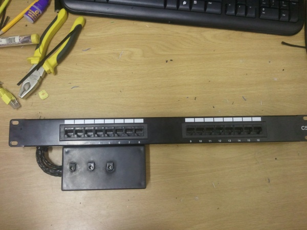
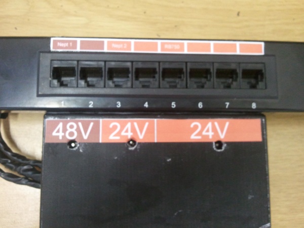
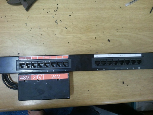
This was basically the result. I used a standard 16 port patch panel. The left 8 RJ45 jacks will powered jacks and the right 8 will be linked to the switch.
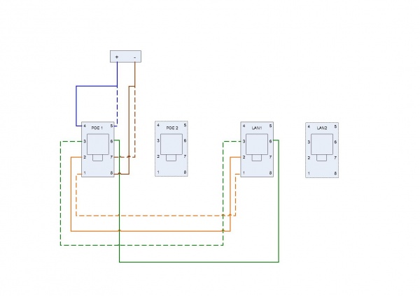
The wiring for the POE pair is as above. Port1 and Port9 is linked, Port2 and Port10 is linked etc.
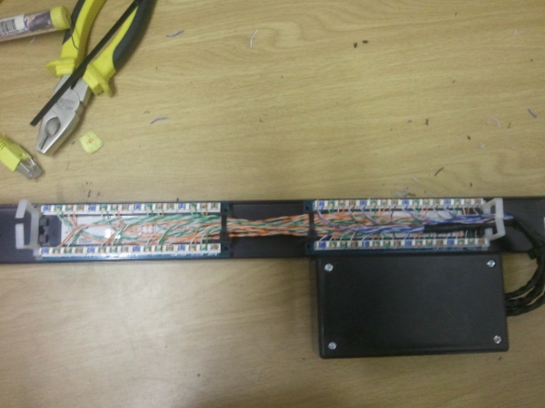
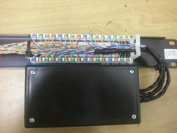
This is the rear view of the patch panel. As you can see, Pins 1,2,3 and 6 of Port1 and Port 9 is linked. Then the power is connected to Pins 4,5,7 and 8.
In My application, I need different POE power for different RB's. I have linked the power of Port1 and 2 for 48V. Port3 and Port4 is linked for a 24V supply. Port 5-8 is then linked to it's own Power Supply.
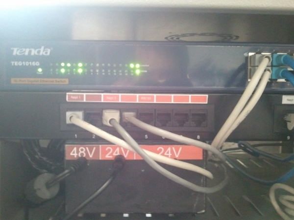
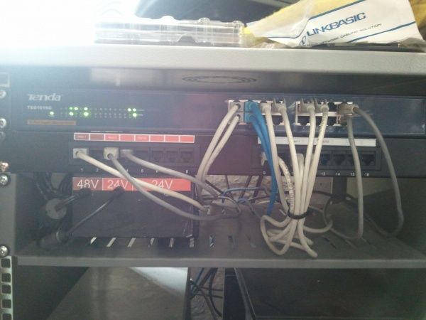
Here as you can see, the POE Patch panel is mounted in my rack and wired into the RB's and patched into the switch. :)
NOTE: This patch panel is not grounded, if the connections to the devices are not grounded, a surge in one device can cause every device to surge (Ubiquiti devices are specifically sensitive to this). I will put together and post a guide by using a 24V Ubiquiti POE and a patch panel (Which will include grounding). Deathrid3r747
